Beginner's Guide to IMU
While discussing robotics, sensors are major elements that can’t be ignored. They become important as they provide an interface to interact with the environment. That is why we have a whole range of sensors for different applications.
Some of the commonly used sensors are:
- Current sensor
- Voltage sensor
- Speedometer
- Light sensor
- Inertial measurement unit
A more elaborative list can be found here
In this blog post, I am only going to talk about my favorite sensor, inertial measurement unit (IMU). This sensor is fun to work with as there are numerous ways one can play around with it.
Note: IMU’s come in wide variety and pricing. So just to be on the same page, IMU that I’ll be considering is a 9DOF IMU with MPU6050 and Honeywell’s HMC5883L.
As the name might suggest an IMU is capable of measuring orientation data and to achieve this it uses a combination of three sensors, namely Accelerometer, Gyroscope, and Magnetometer. Before moving on to how these work some definitions are necessary (yeah boring things):
- Degree of Freedom (DOF) – number of the directions in which independent motion can occur (Source: Google)
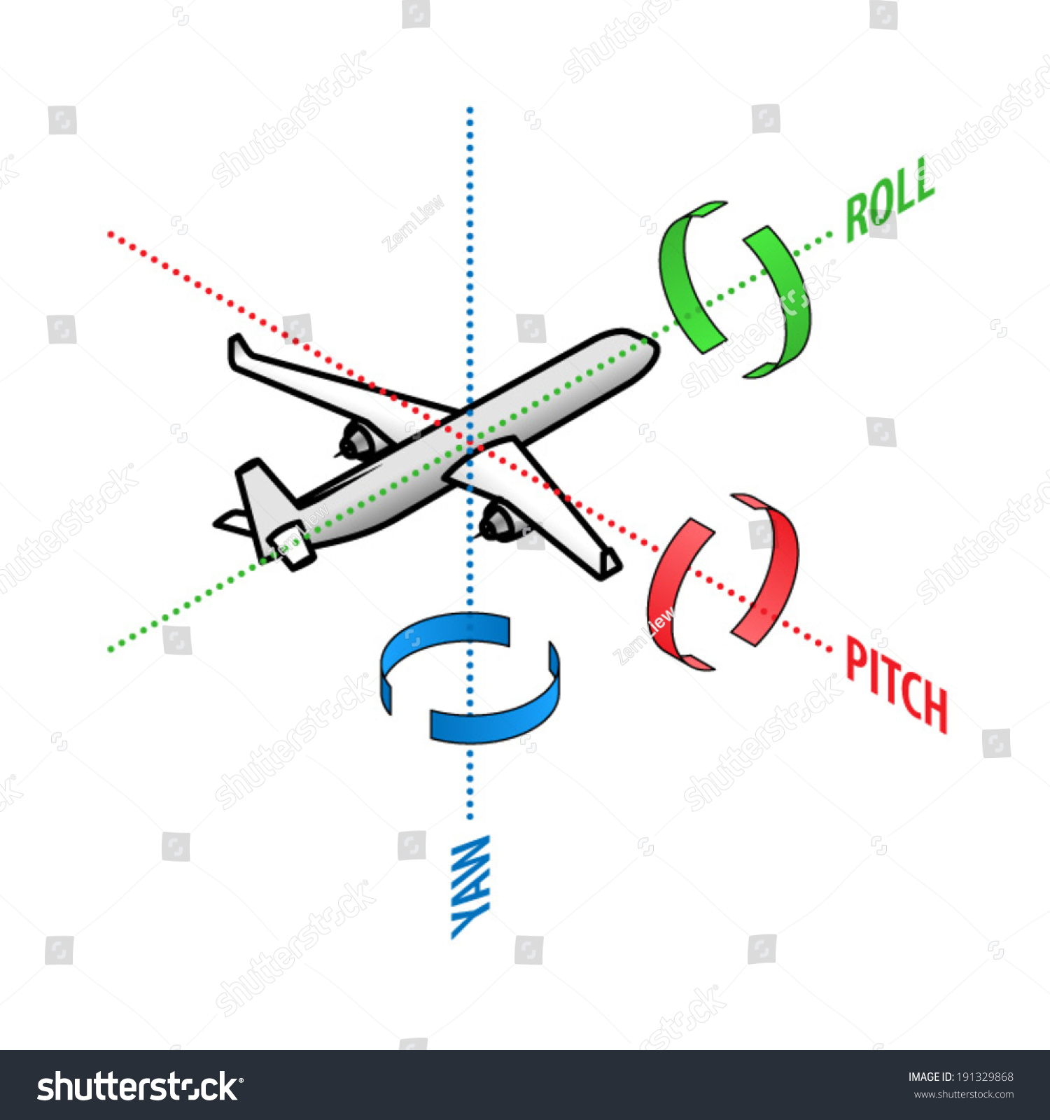
- Roll – Pitch – Yaw – I believe an image would explain this better. So here it is. For us roll axis will be X axis, the pitch will be along Y axis and yaw along the Z axis.
Accelerometer
First, we’ll discuss accelerometer. Briefly, accelerometer measures and tells you the amount of force (acceleration) it is experiencing in X, Y and Z direction. Now, this data makes sense in orientation because of gravity. We know that if an object is not moving it will experience acceleration only due to gravity (neglect the other minimal forces). The direction of gravitational force is always same with respect to the earth’s frame but based on the orientation of IMU, it will experience different amount of acceleration along the three axes. These acceleration values can give us roll and pitch values.
pitch = 180 * atan2(accelX, sqrt(accelY*accelY + accelZ*accelZ))/PI;
roll = 180 * atan2(accelY, sqrt(accelX*accelX + accelZ*accelZ))/PI;
Above formulas can be derived. Give it a try!
Gyroscope
Talking about the gyroscope, it measures the angular velocity along the three axes. So it is not directly able to predict roll, pitch or yaw. But as we can see integrating angular velocity over time gives us the angle, which can be used to measure the change in roll, pitch and yaw. Although this technique is not used that much as the readings of the gyroscope are very erroneous.
Magnetometer
The third component of our IMU is the magnetometer. This is where I have seen people facing difficulties. It is a device capable of measuring magnetism. It is able to help us find orientation using the earth’s magnetic field, similar to a compass. As in accelerometer one can use the X, Y and Z magnetometer readings to calculate yaw.
mag_x = magReadX*cos(pitch) + magReadY*sin(roll)*sin(pitch) + magReadZ*cos(roll)*sin(pitch)
mag_y = magReadY * cos(roll) - magReadZ * sin(roll)
yaw = 180 * atan2(-mag_y,mag_x)/M_PI;
Now the most common question asked is, why can’t we calculate yaw using accelerometer itself? The reason is in the physics. As you notice that accelerometer works on the fact that gravitational force is always constant in direction i.e. towards the earth, we use this fact but in case of yaw, the yaw axis is perpendicular to gravitational force, so if we keep roll and pitch same and just change the yaw angle we will not be able to measure any difference in accelerometer values. Hence accelerometer fails to measure yaw.
These are all the concepts needed to understand IMU. For using an IMU sensor with a microcontroller few more things need to be learned. There are many references on the internet for the same. Following are a few:
- Excellent tutorial explaining physics of accelerometer and gyroscope here.
- Formulas here
- DCM tutorial
- Cool animations here
- An IMU library for Arduino here
- Arduino tutorial to get started here
Calibration techniques
From this point, I assume that you’ve understood how IMU works and have tried to get the roll, pitch and yaw values using the sensor. If not done, please do, as the following section will not make sense until you’ve played with the sensor. The more you play, the more you understand its behavior. If you’ve done the above things and are getting good values then it is great, but if not (which is the most probable case) you are still fine, this section will help you. One of the important points of getting correct values is calibration of sensor instead of using the raw data. There are different ways for calibrating the sensor like measuring the value along three axes and manually calculating offset and scaling term. My approach relies more on a tool known as Magneto.
The tool can be found here. Usage instructions are already available on the website. Briefly what this does is, you give it the readings of the sensor and it tries to fit those readings on an ellipsoid and return the equation of the ellipsoid in form of a scaling matrix A and bias b. To make sure that the tool works well, try to make sure that the file you are uploading as input readings contain the values in all the three rotations, such that the ellipsoid is completely covered. This tool is popularly used for calibrating the magnetometer but can be used for accelerometer calibration as well. A helpful link regarding calibration: Calibration techniques
Common errors and debugging methods
This is almost everything you can do theoretically to get good values without making the system too complex using filters. There is a possibility that the data you are getting is not as expected. So, how to correct it? Simple, debug the system! This is the place I’ve found many people facing a hard time. Well, it is not that difficult, just use your intuitions and understanding of physics. From here it is all about analyzing data.
Consider a case where changing pitch angle is changing your roll value too. This is not expected (minor changes are ok). So how will you go about finding the fault? Let’s break it into steps. So you are observing that pitch is affecting roll, check if it is true vice versa i.e. roll is affecting pitch or not? If yes, then probably the formulas are wrong somewhere. Derive the formulas again just to be sure or look up on the internet. If the formulas are correct then maybe you need to go down to a more basic level. Now analyze the values that are being used in roll and pitch calculation. Observe how they are getting changed when you change the orientation along one axis only. If you observe that changing orientation along one axis changes values along other axes, then there might be a mistake in calibration code. Follow this top down approach until you reach a point where the observed values are as expected. Try to find what you did wrong in the step above it. If you’ve reached the bottom most layer i.e. the data being sent by the IMU itself is faulty, then probably the sensor has gone bad (very fewer chances that this will happen). You can either provide a compensation factor in the code itself to take into account the error in sensors reading (if possible) or maybe it is time to change the sensor. That’s it regarding IMU, mostly IMU’s readings are prone to drifting when used in long time setting. But there are techniques such as Kalman filter that make using IMU in a real-time situation more reliable. Google it!